Friday 14 December 2012

Ethernet!

Sure Electronics sells a cheap ($10) SPI Ethernet module based on the ENC28J60 controller. This is a different controller to the one in the Arduino Ethernet shield so isn't supported out-of-the-box by the Arduino IDE. (Interestingly it has no hardwired MAC address: you supply your own, the thinking presumably being that the odds of picking one already on your home LAN are effectively zero.)


I soldered a 6-way male connector to the small connector at the opposite end of the board from the RJ11 socket and stuck it in a breadboard for testing. Since this is an SPI device, only four connections are needed to the Arduino, besides power:

ArduinoSPIENC28J60
12MISOData Out
11MOSIData In
13SCLKClock
8CSChip Select

Luckily there is no shortage of libraries for it! I counted at least four during my search but settled on two. The first I found was by one Doctor Monk and worked pretty well, the only problem being that it only provides a web-server, not a general TCP/IP stack. 

The next one was EtherCard from JeeLabs which is downloadable at GitHub. Although it modestly claims to be a work-in-progress, it ships with fully 15 examples demonstrating everything from DHCP and DNS to Twitter and Pachube. The only gotcha I found with it was that its examples use pin 8 on the Arduino for Chip Select and I had been using pin 10 previously for this.

Friday 14 September 2012

Interval Handling on Arduino

When designing devices which never reset and which need to be aware of time, one thing to beware of is the millisecond timer rolling over. According to the reference manual, this happens after about 50 days. If your device is designed to be powered on for short periods of time and happens to be on while this timer overflows, then it will fail to power off and you'll have to power-cycle it.
This little class avoids this problem by watching for the overflow and calculating the interval correctly.

Saturday 1 September 2012

USB IR Receiver


This is a little USB infrared receiver based on an original design by Ben Ryves. It pretends to be a USB keyboard and works by mapping NEC IR codes to keystrokes --- controlling the chosen application through its keyboard shortcuts. (VLC is a good choice of application because it's possible to change its shortcuts to match the ones sent by the receiver.)

I slightly simplified the hardware removing a switch which the original used to send different sets of key-codes, for two applications without programmable shortcuts. The modified circuit diagram is below.
(Note that the circuit must run at 12 MHz. I think this was due to the timing of the IR reception routine.)

I also simplified the software, removing a detection routine for the SIRCS protocol. Ben's original software is here, while my modifications are here.  The USB stack is V-USB: this is a nice simple example of getting started with it.

The software detects codes sent by a Newsky DVB-T remote control, seen below.
An easy way to discover the type of your remote control and the codes it sends, is with Ken Shirriff's handy IR library for Arduino; use the IRrecvDump sketch.

Tuesday 17 July 2012

Frankenstein's Thermometer Mk2

Well it's been just over a year since this blog started and what better way to celebrate than revising an old project? I'd had a look at Frankenstein's thermometer before, using a neat trick with a mono jack plug and a stereo socket to switch the power. However I wasn't really pleased with this arrangement, because it separated the thermistor from the main box when it wasn't in use.

The idea was to upgrade the firmware to put the ATtiny into deep sleep after a short time. The complete code is now:

The main additions are:
  • the sleep() routine which causes the ATtiny to enter a power-down mode,
  • the PCINT1_vect which wakes it up again when the push-button is pressed.
The port PB1, which the push-button connects to ground, generates PCINT9. On the ATtiny84, there are two pin-change interrupts, PCINT0 and PCINT1. The former handles pin change signals on Port A, while the latter handles those from Port B. Our handler simply checks whether the interrupt has woken us up, or was to change the units of temperature.

The sleep routine switches off all of the LEDs and the ADC before putting the ATtiny to sleep. When it wakes up again, the ADC must be re-enabled.

With the new software installed,  the device consumes about 11mA when on but 0.16mA when off. With a nominal capacity of 1000mAh, this would drain the batteries in about 6000 hours (or 250 days). This was a bit surprising, as was the discovery that this current was still drawn when the AVR was removed altogether. This indicated that the source of the drain was the voltage divider comprising the thermistor and a 10k resistor. (See the circuit diagram in the original posting.) At room temperature, the current drawn would be 3v/20k or 0.15mA.

Rather than complicate the circuit with a MOSFET switch, we decided simply to increase the value of the bias resistor from 10k to 47k. This reduced the current by a factor of 4 increasing the battery life to over 2 years. (The calculation of the Thermistor equation has been cleaned up a bit too: the original made the assumption that the 10k resistor would cancel the thermistor's resistance at 25C.)

Thursday 5 July 2012

Pulse Width Modulation

The LED is an interesting beast and dimming one is an interesting problem. Unlike an incandescent bulb, simply changing the voltage across it does not work. The diagram below shows why: its I-V curve is almost vertical around Vd and any lower voltage will cause it to turn off. (It's also why a current-limiting resistor is essential: connecting it to a supply even slightly greater than Vd will cause a huge current to flow, destroying it with a pop.)


In the analog world, varying the brightness of an LED might be achieved with a dependent current-source, involving an op-amp perhaps. However in the digital world of this blog, the only way is to vary a square-wave's duty-cycle (the ratio of on-time to off-time) quickly enough for flickering to be indistinguishable to the eye, so the average brightness is perceived. This method is known as pulse-width modulation or PWM.

On Arduino, PWM is achieved in hardware using the analogWrite() function. Confusingly this does not use the analog input pins, but a subset of the digital I/O pins. However analogWrite() provides limited control, for one thing the frequency is fixed; should more control be required you have to go under the Arduino API (this excellent tutorial has the answers).

Although the ATtiny85 also has hardware PWM, your author was unable to make it work without flicker using the ATtiny Arduino core, probably because the internal oscillator was running too slowly at 1MHz. Software bit-banging, as shown in the following sketch, did work well enough at this frequency.

By varying the duty-cycle from low to high and back again, this little sketch brightens and dims an LED attached to the desired pin in a manner similar to Apple's breathing LED. Varying the delay parameter also allows control over the rate of breathing.

Thursday 21 June 2012

Transistortester

One of the most enjoyable distractions of the past year has undoubtedly been MIT's online course in Circuits and Electronics. This sparked a renewed interest in discrete electronics which naturally led to the idea of measuring various parts' characteristics using AVRs. (The link with Arduino probably arose from a tutorial showing how to measure capacitance.)

Needless to say, once the idea had germinated it was only a matter of time before I spotted that someone else had done it, and much more thoroughly than I had ever planned to. An initial siting on Dangerous Prototypes led to the original German site where one Markus Frejek had done a magnificent job identifying and measuring characteristics of 15 different kinds of Semiconductor device (plus Resistors and Capacitors) using an AVR. His original design is downloadable here --- this package contains his circuit diagram with a neat transistor latch to turn off the voltage regulator when powering-down the AVR. (I didn't go with this in the end, preferring to use a momentary push-button to power it on.)

I built this circuit over the course of a day and I had translated the strings into English when I discovered that Markus's original announcement in early 2009 had led to a huge thread on mikrocontroller.net (which continues today!). His code had been taken up and extensively modified by Karl-Heinz Kübbeler. I went with the latest version (096k) which still works with the original circuit diagram.

The new software which is quite well packaged, is certainly the biggest AVR program I have seen. I edited the Makefile for the following settings:
#CFLAGS += -DNO_AREF_CAP
#CFLAGS += -DPULLUP_DISABLE
PROGRAMMER=avrisp
PORT=/dev/ttyUSB0 -b 19200
The file Transistortester.h should also be edited for the exact values of the resistors connected to the analog inputs, R_L_VAL and R_H_VAL --- test them with a multimeter before soldering them up. (It is probably worthwhile to use 1% tolerance parts.)  Then make && make upload && make fuses will program the microcontroller correctly.

A poor photo of my completed build on stripboard is shown below measuring an IN4148 diode. About the only change I'd make to this great project would be to introduce a software mapping layer for the connections between the AVR and the LCD data pins. (The default connections require a lot of cut-tracks and fiddly crossing-wires for the backpack arrangement I went with.)

It fits perfectly in an old perspex iPod nano case I found lying around!

Friday 13 April 2012

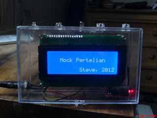
Mock Pertelian


The last post concluded with a shopping list of requirements for a workable wireless display. The picture above shows a prototype of such a thing. In particular:
  • It doesn't try to be too clever: it uses an XBee as a wireless serial port and lets an ATMega do the heavy lifting, driving the display in 8-bit mode.
  • It is compatible with an existing lcdproc driver, pertelian, hence the name.
  • It bites the bullet and uses an external supply rather than batteries.
The backlight is turned on by touching a metal bolt on the top of the case. This bolt is wired to one of the ATMega's analog inputs via a solder tag. The case itself is a cheap perspex box costing about £1 from eBay.

The circuit diagram and Arduino sketch are shown below.


Update: after running for a week or so at 9600 baud, the 20x4 display was messed up. Although I never got to the bottom of it, the fault lay in the transmitting XBee: unless it was power-cycled, the problem persisted through reboots of the display and the box running LCDd. A successful workaround was to run all parts of the system at 57600 baud, i.e., both serial ports and both XBees.

Friday 17 February 2012

Heroic Failures #1

This is the first in a (hopefully short) series of posts describing things which seemed possible beforehand but which turned out unsatisfactorily. It is inspired by a quote from Fred Brooks (via Nat) "Good judgement is the result of experience ... Experience is the result of bad judgement."

The initial motivation was dissatisfaction with the fact that all current (to my knowledge) lcdproc displays must be tethered to their host by either USB or Serial and that they might be much more useful if they could be positioned where they were needed.  When this was coupled to the observation that XBees are pretty smart and have lots of I/O, it seemed that driving a 4-line LCD display directly from an XBee using a couple of AA batteries might be a runner. The circuit is shown below and shows the display being driven in 4-bit mode with a couple of extra lines for EN and RS (I could only find a Series-1 Eagle part and used a Series-2 XBee so some of the pin names are a bit off).


One hacked lcdproc driver and some low-level XBee and LCD C-programming later, it worked... but only just!
  • The display wouldn't work properly with 3.3v: it required 5v and hence another regulator for the XBee, e.g., an Explorer Regulated breakout board,
  • It also wouldn't work (for very long anyway) on batteries: when its backlight was on, the display drew 150mA,
  • Maintaining an out-of-tree driver (for lcdproc) is painful,
  • It is extremely slow (about 1 char/sec). This is because each bit is framed in an XBee packet (thus requiring ~100 bytes to get one character to the display).

Monday 30 January 2012

Twilight Mk2


The picture shows an updated version of Twilight driving a 3W LED inside a salt crystal. The new circuit:
  • does away with the LEDs, using the controlled light itself as an indicator,
  • ditches the variable resistor, using a long-press on the switch to indicate the light-level at which to switch on,
  • stores this light-level in EEPROM to preserve it across power cycles
  • uses an ATtiny85 for a smaller footprint
When switched on for the first time, the light is flashed quickly four times. When the environment reaches the desired level of twilight, the user presses the switch for two seconds to indicate this light level is to be stored. The light is then flashed slowly twice.

A circuit diagram and sketch (for Arduino 1.0) are shown below.